The Electrical Machines Laboratory provides a comprehensive environment for studying the operational behavior, performance characteristics, and control principles of electrical machinery. The laboratory focuses on experimental analysis of DC machines, induction motors, synchronous machines, and transformers, enabling investigation of torque–speed characteristics, efficiency evaluation, loss analysis, and dynamic response under various loading and excitation conditions. It supports both instructional and research activities aimed at understanding machine modeling, electromechanical energy conversion, and practical aspects of machine control and diagnostics, and the following equipment are available in this laboratory.
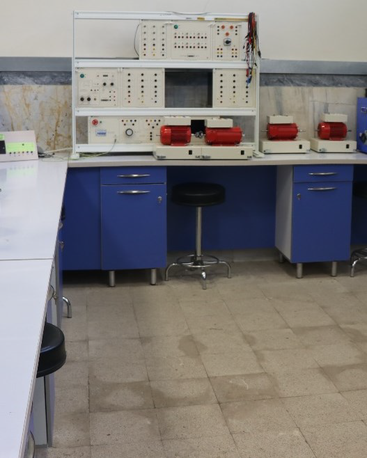
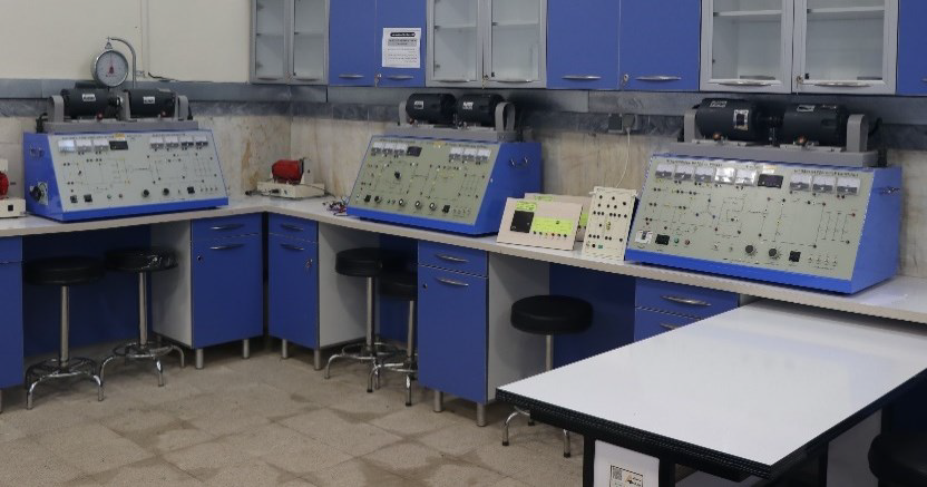
This laboratory is designed to enhance students’ practical experience and familiarize them with the internal structure, physical principles, and performance of various electrical machines. By learning the basic concepts of electricity and magnetism, students can perform a variety of experiments involving different types of electrical machines such as DC and AC motors and generators, as well as single‑phase and three‑phase transformers. Through hands‑on work with real equipment, they study and analyze characteristics and operational phenomena such as excitation, series and parallel connections, speed control, and load testing of electrical machines. The Electrical Machines Laboratory comprises two laboratory sets—Machine I and Machine II— containing a total of four multifunctional training benches, which are described in the following section.
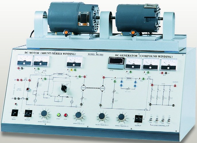
A. DC Shunt and Series Motor / DC Generator Training System
Objectives of Experiments (Figure A):
- Examine the starting and load characteristics of DC shunt and series motors.
- Determine torque, losses, and efficiency of DC shunt and series motors.
- Investigate the relationship between motor speed and field excitation in DC motors.
- Record and analyze load characteristics of DC generators.
- Study the characteristics of cumulative and differential compound DC machines.
- Measure the rotational speed of the generator and analyze output parameters.
- Calculate losses and efficiency of the compound DC generator.
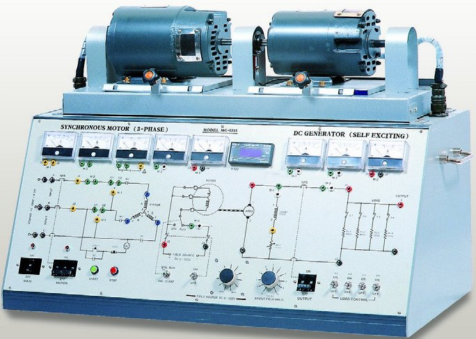
B. Three‑Phase Synchronous Motor / DC Generator Training System
To perform experiments (Figure B):
- Study of the starting method and synchronous characteristics of synchronous motors.
- Examination of the V‑curve characteristics of synchronous motors.
- Calculation of losses and efficiency of synchronous motors.
- Analysis of the load characteristic curve of a self‑excited DC shunt generator.
- Study of field and output characteristics of the shunt generator.
- Measurement of speed and analysis of generator output characteristics.
- Calculation of losses and efficiency of the DC shunt generator.
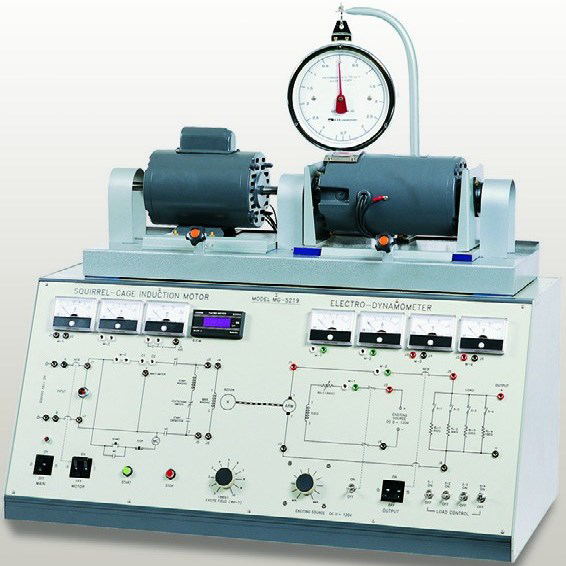
C. Induction Motor Teaching System (Squirrel‑Cage Type) with Dynamometer
To perform experiments (Figure C):
- Study of starting characteristics of squirrel‑cage induction motors.
- Reversing the rotation direction of squirrel‑cage induction motors.
- Measurement of speed and torque in squirrel‑cage induction motors.
- Determination of torque, efficiency, and output power of squirrel‑cage induction motors.
- Use of an electrodynamometer (torque meter).
- Measurement of torque using a dynamometer device.
- Use of an independently excited DC generator.
D. Electrical Machines II Experimental Set with Manual and Computer‑Based Operation Capability
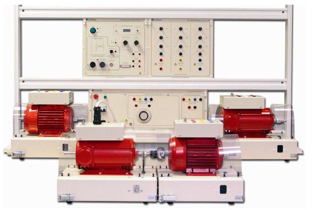
As access to energy resources becomes increasingly limited, it is crucial to use them in the most efficient manner. Engineers and technicians must understand which machines and motors are most suitable for specific applications, how they generate electricity with minimum losses, and how they perform under electrical loads, voltages, and currents. For example, is it more effective to use a DC motor or a DC generator as a source of energy? How can maximum efficiency be achieved under operational requirements, and how can energy be distributed and utilized optimally? In this laboratory system, comprehensive educational tools are provided to facilitate experiments and instruction regarding transformers and motors/generators. The laboratory setup is designed according to international electrical and safety standards, offering most of the necessary electrical measurements, instrument settings, and control functions for DC, AC, and synchronous machines. All units are equipped with internal protection, fuses, and safety covers against accidental contact with active electrical terminals. Each machine, rated at 250–750 W, is fully enclosed and mounted on a universal metal stand with a transparent protective cover. The setup allows for machines to be easily installed or removed from the panel base and enables flexible connection of different machines through coupling shafts. The stand is equipped with a built‑in library cabinet, drawers for accessories, and measurement devices, all neatly organized for instructional clarity. Separate analog and digital measuring instruments, along with connection cables, are provided in portable cases. The system, designed for both manual and computer‑assisted operation, enables students to perform a wide variety of experiments related to machine performance, energy conversion, and efficiency evaluation.
The Stand system includes the following components:
1. Compound DC Machine:
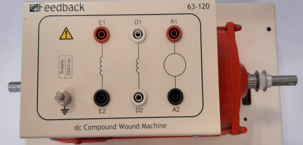
The DC compound machine can be used to compare the specifications of DC machines with different winding configurations. Machines equipped with series, shunt, or compound windings operate as both motors and generators when coupled.
- Rated power: 250 W (continuous)
- Rated speed: 2000 rpm
- Maximum speed: 6000 rpm
- Required voltage: 220 V DC
- Operates as a motor or generator in series, shunt, or compound mode
- Shaft diameter (both ends): 12 mm
2. Single‑Phase Induction Motor (Capacitor‑Start / Capacitor‑Run Type):
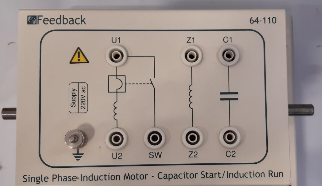
This machine is widely used for experimental purposes. The main and auxiliary windings are identified, and their influence on starting characteristics, operation, and performance is examined.
- Rated power: 250 W
- Rotational speed: up to 2850 rpm at 50 Hz
- Required supply: 220 V single‑phase AC
- Shaft diameter: 12 mm
- Double‑ended shaft
3. Three‑Phase Induction Motor (Squirrel‑Cage Type, Dual Voltage):
The squirrel‑cage three‑phase induction motor is one of the most energy‑efficient and widely used three‑phase machines in industry. Among various experimental topics, this motor can be employed to study aspects such as rotation direction reversal, torque characteristics, and speed control.
- Dual voltage rating: Δ 220 / Y 380–415 V (50 Hz)
- Rated power: 250 W
- Rotational speed: up to 2980 rpm at 50 Hz
- Required supply: Three‑phase AC, Δ 220 / Y 380–415 V at 50 Hz
- Shaft diameter: 12 mm
- Double‑ended shaft
4. Vibrating‑Field Dynamometer:
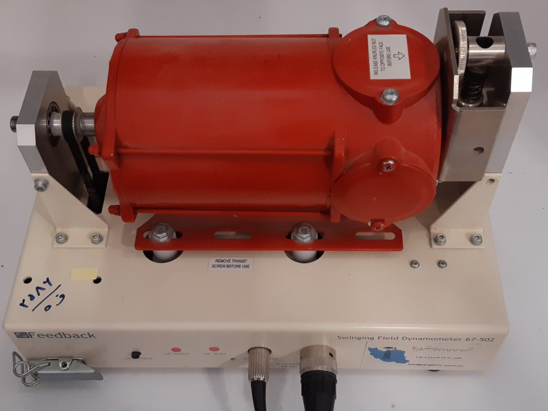
This is a multifunctional machine loading system, which includes an electrical dynamometer integrated with a tachogenerator for speed and torque control, along with complete wiring connections. It can be used manually for applying load torque to the motor or for controlling the generator speed, operating as a constant‑speed motor.
- High‑accuracy torque transducer output
- Output torque proportional to the applied load under both motoring and generating conditions
- Equipped with a central test lever for torque loading and winding torque measurement
- Directly connected to a modular speed and torque control unit
- Permanently coupled with a DC tachogenerator
- Maximum speed: 5000 rpm
- Maximum torque: 3 N·m
5. Three‑Phase Synchronous Motor / Generator with Slip‑Ring Rotor:
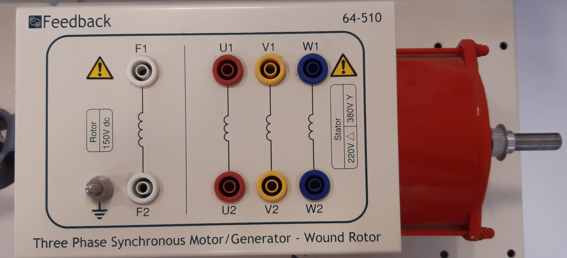
The three‑phase synchronous machine can be used either as a motor or as a generator. The requirements for startup, synchronization, load characteristics, and operation as a synchronous condenser are included. The synchronous module also shows how a three‑phase alternator can be synchronized with an existing power source. This synchronization feature allows operating in parallel with other systems, providing the possibility to perform experiments such as load sharing and power factor correction. The device can also be used as a synchronous generator for studying output characteristics and torque specifications.
- Suitable for operation as motor or generator
- Voltage: 240/415 V
- Power: 200 W
- Synchronous speed: 3000 rpm, 50 Hz
- Required supply: three‑phase AC 220/380 V or 240/415 V (Δ/Υ)
- Rotor excitation supply: 100 V DC
- Shaft diameter: 12 mm
- Double‑ended shaft
6. Universal Motor (Series Type):
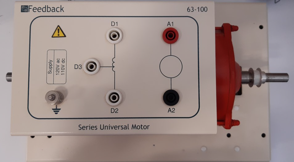
The series universal motor is a simple, multifunctional, and highly versatile device that can operate with either a DC supply or a single‑phase AC supply. The comparison between performances under both power supplies can be demonstrated using compensating windings connected in series with the armature. All electrical machines in this system are of the MS‑0604 series, equipped with fully enclosed and protected electrical connectors. The system includes square‑type clutches and mechanical couplings for securing or releasing paired machines.
- Rated power: 250 W (continuous)
- Maximum speed: 6000 rpm
- Required supply: 220 V DC or single‑phase 220 V AC, 50 Hz
- Double‑ended shaft with 12 mm diameter
7. Universal Power Supply:
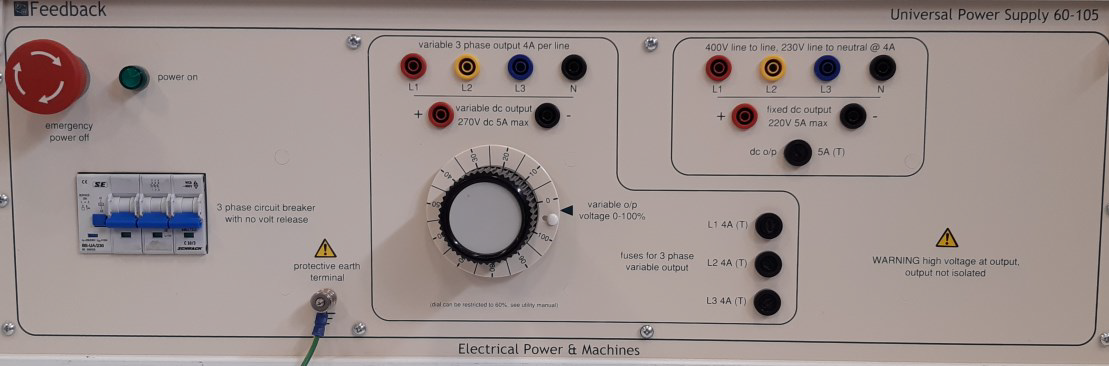
- Equipped with protective circuitry
- Three‑phase: nominal voltage up to 400 V AC, line current 4 A
- Single‑phase: 3 outlets, each with nominal voltage up to 230 V AC, line current 4 A DC
- Three‑phase: 400 V line voltage, 230 V single‑phase voltage, 220 V constant DC 10 A
- Single‑phase power distribution
- Equipped with earth (ground) connection
8. Single‑Phase Transformer:
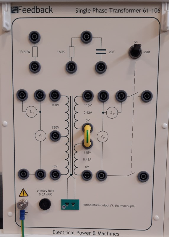
- Multi‑winding coils for series and parallel connections
- Windings rated at 400 V, 230 V, and two windings of 115 V
- Apparent power: 100 VA
- Mimic panel for transformer winding connections
- Equipped with earth (ground) connection
9. Three‑Phase Transformer:
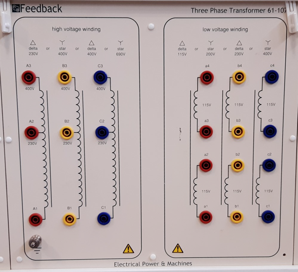
- Primary side with star or delta connection, voltage 415/380 V AC
- Secondary side: two 115 V windings per phase, 0.43 A
- Apparent power: 300 VA
- Connections via safety‑covered sockets with colour‑coded 4 mm terminals on the mimic panel
- Equipped with earth (ground) connection
10. Three‑Phase Resistive Load:
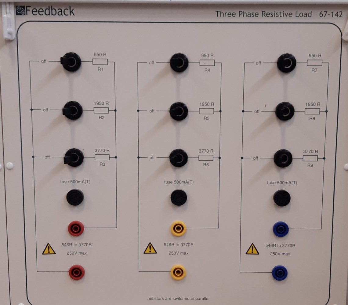
- Three switched resistive load banks
- Seven resistance levels per bank
- Resistance range: 547 – 3770 Ω per bank, 100 W per bank
- Total three‑phase load: 300 W at 400 V (star) or 230 V (delta) connection
- 0.5 A fuse protection
- Equipped with earth (ground) connection
11. Three‑Phase Capacitor:
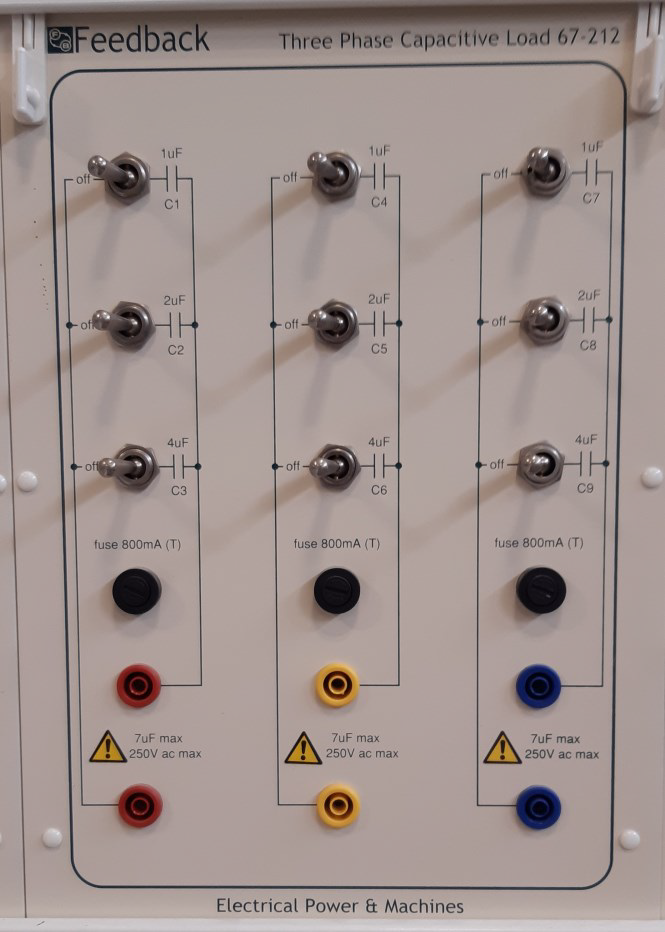
- Three switched capacitive load banks
- Seven capacitance levels per bank
- Capacitance range: 1 – 7 µF per bank
- Reactive power: 116 VAR at 230 V, 50 Hz per bank
- Total three‑phase load: 348 VAR at 400 V (star) or 230 V (delta) connection
- Protected by 0.8 A fuse per bank
- Equipped with earth (ground) connection
12. Three‑Phase Inductive Load:
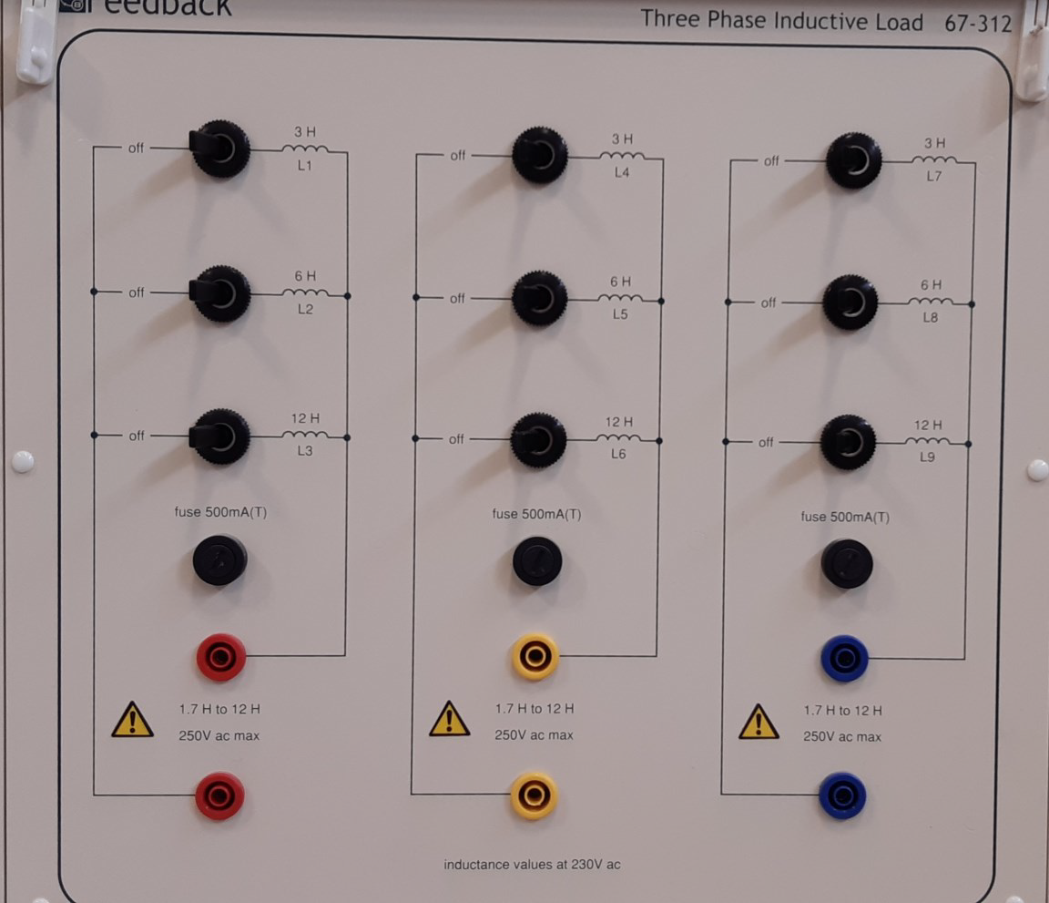
- Three switched inductive load banks
- Seven inductance levels per bank
- Inductance range: 1.7 H – 12 H per bank
- Reactive power per bank: 100 VAR at 230 V, 50 Hz
- Total three‑phase load: 300 VAR at 400 V (star) or 230 V (delta) connection
- Protected by 0.5 A fuse per bank
- Equipped with earth (ground) connection
13. Synchronizing Lamps:
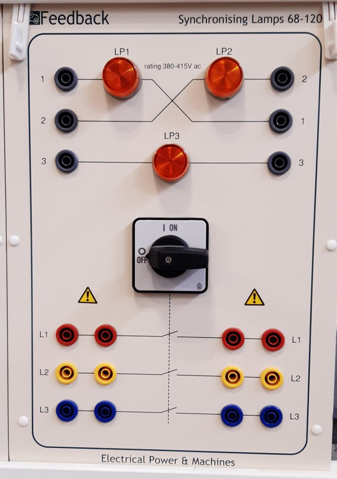
- Initial synchronization is performed using phase‑indicator lamps arranged in a delta configuration
- Synchronization technique can be based on bright‑lamp or dark‑lamp methods
- A power switch is provided for connecting the systems together
- Accommodates single‑phase or three‑phase operation
- Equipped with earth (ground) connection
- Operating voltage range: 380 – 415 V
14. Speed and Torque Control:
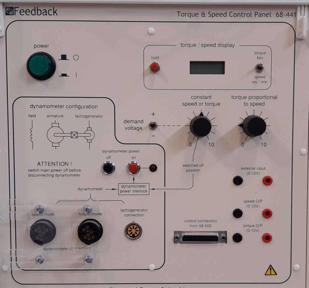
- Used in conjunction with the dynamometer unit
- Provides manual control of torque and speed
- Enables constant torque or torque proportional to speed control
- Equipped with a digital display for speed or torque indication
- Compatible with Multichannel panel operation
- Speed range: ±5000 rpm; Torque range: ±3 N·m
- Power supply: 220 – 250 V AC, 50 Hz
15. Multi‑Channel Input/Output Unit with USB Interface and Software:
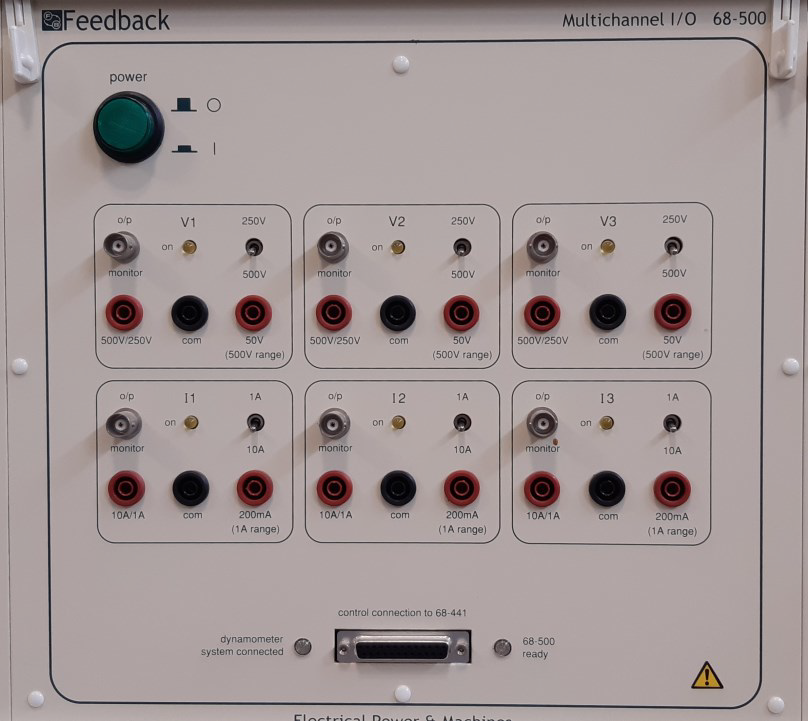
- The software is used for evaluating the behavior of electrical systems
- The precision instrument software displays the following parameters on the screen:✓ AC and DC voltmeter and ammeter✓ DC wattmeter✓ Single‑phase and three‑phase wattmeter✓ Phase meter✓ VA meter
- Includes data display capability
- Six isolated channels
- Three voltage and three current isolated channels
- Power supply: 230 V AC or 120 V AC, 50/60 Hz