The Vibrations and Machine Dynamics Laboratory focuses on the experimental investigation of dynamic behavior in mechanical and structural systems, including vibration analysis, modal characterization, rotordynamics, and machine condition monitoring. The laboratory supports both academic research and industry‑oriented applications involving dynamic testing, signal analysis, and system diagnostics, and the following equipment are available in this laboratory.
1. Planetary gear system
Objective of the Experiment:
To determine the mechanical efficiency of the planetary gear system.
Theory of the Experiment:
The planetary gear system is used in machine tools, hoists, automobile differentials, and other applications where high gear ratios are required in a compact space, and sometimes with misaligned input and output shafts. In a planetary gear system, there is at least one gear whose axis rotates around the axis of another gear.
The experimental apparatus consists of a sun gear (S), three planet gears (P), and an arm (A). The housing that holds the planetary gear assembly includes an internal gear, which during the experiment is locked by a fixed beam equipped with a displacement gauge. This setup is used to measure the torque reaction of the housing (see figure below).
2.
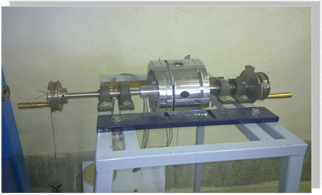
Critical Speed and Whirling of Rotating Shafts
Objective of the Experiment:
Observation and investigation of the critical speed phenomenon in rotating shafts.
Theory of the Experiment:
At certain rotational speeds, shafts become dynamically unstable and begin to whirl intensely. These speeds are referred to as critical speeds. A critical speed occurs when the frequency induced by shaft rotation matches the natural frequency of the beam in one of its vibrational modes, resulting in resonance and amplification of the beam’s oscillation amplitude. This can lead to shaft failure and extremely high forces on the bearings, potentially causing them to break.
Additionally, at critical speeds, the shaft deflection may exceed the elastic limit, causing the shaft to rotate in a bent shape even at non-critical speeds. In generators and turbines, the clearance between rotating shafts and stationary components is minimal, and shaft deflection may lead to contact between them, causing damage.
Several factors influence this phenomenon, including shaft weight distribution, asymmetry, uneven concentrated loads, and bearing friction.
The test shaft is mounted in such a way that it does not generate bending moments in the bearings, thus behaving like a beam with pinned supports.
In this experiment, the effect of concentrated loads (in the form of disks mounted on the shaft) on the beam’s critical speed is studied, and the beam’s own weight is neglected. The figure below shows the test apparatus.
3.
Transverse Vibration of Beams
Objective of the Experiment:
Investigating the natural frequency in transverse vibration of beams using Dunkerley's Rule.
Theory of the Experiment:
When a beam of span length ( L ) and weight ( W ) is subjected to external loads ( W_1, W_2, dots ), according to Dunkerley's Rule, the following relation can be written:
[ frac{1}{f2} = frac{1}{f_02} + frac{1}{f_12} + frac{1}{f_22} + dots ]
Where:
- ( f ): Natural frequency of the beam considering its own weight and external loads
- ( f_0 ): Natural frequency of the beam considering only its own weight
- ( f_1, f_2, dots ): Natural frequencies due to individual external loads assuming the beam is weightless
When the transverse vibration of a beam coincides with its natural frequency, the vibration amplitude gradually increases, accompanied by significant noise, and may lead to beam failure.
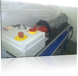
Apparatus and Equipment:
A rectangular cross-section beam is mounted with one end on a pinned support and the other on a roller support. A 24V DC synchronous motor equipped with a speed controller and vibrator is attached to the beam (see figure on the next page).
The beam is made of steel with a cross-sectional area of [value missing] mm² and a total length of 85 cm. Considering the fixed clamp, the effective length is 79.1 cm. The beam’s mass is 2080 grams.
The motor, with an eccentric oscillator, safety cover, sliding ring, and bolts for attaching weights, has a mass of 1915 grams. Five cylindrical weights, each 10.44 mm thick, 80 mm in diameter, and weighing 400 grams, are used.
To reach the critical vibration threshold (i.e., when the beam vibrates at its natural frequency), a speed control device is used. A sensor protects the system and displays the beam’s vibration frequency on the corresponding indicator.
4.
Simple Pendulum
Objective of the Experiment:
Experimental investigation of the oscillations of a simple plastic and steel pendulum in a plane, and comparison of the experimental results with theoretical predictions.
Theory of the Experiment:
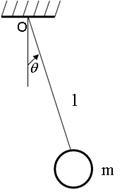
One example of free undamped vibrations is the simple pendulum. A small mass or bob with negligible weight is suspended vertically by a string from a pivot. When the bob is displaced from its vertical position, it oscillates periodically and regularly about that position.
If the motion is confined to a single plane, the generalized coordinate describing the motion is the angular displacement from the vertical. The string acts as a constraint, forcing the pendulum bob to move along a circular path around the pivot.
5.
Compound Pendulum
Objective of the Experiment:
To investigate gravitational acceleration using the oscillations of a compound pendulum and to examine the radius of gyration of the pendulum rod about its center of gravity.
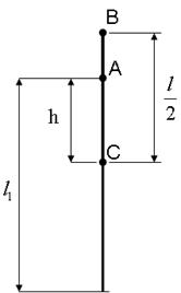
Theory of the Experiment:
The compound pendulum consists of a steel rod with a diameter of 8 mm and a length of 99.9 cm, which is supported by an alloyed aluminum knife-edge (see figure below).
The period of this pendulum is obtained from the following relation:
[ T = 2pi sqrt{frac{I}{mgh}} quad text{or} quad T = 2pi sqrt{frac{k^2}{gh}} ]
Where:
- ( T ): Period of oscillation
- ( I ): Moment of inertia of the body about the suspension point
- ( m ): Total mass of the pendulum (440 grams = 0.440 kg)
- ( g ): Acceleration due to gravity
- ( h ): Distance from the center of gravity to the suspension point
- ( k ): Radius of gyration of the rod about its center of gravity
The steel rod has a mass of 365 grams, and the aluminum knife-edge has a mass of 75 grams, giving a total mass of 440 grams.
6.
Governor
Objective of the Experiment:
To examine the operation, sensitivity, and stability of mechanical governors.
Theory of the Experiment:
Governors are used to control the speed and power of prime movers such as diesel engines, steam turbines, hydroelectric turbines, and others. Governors are classified into three types:
- Mechanical Governor (the subject of this experiment)
- Electromechanical Governor
- Electronic Governor
In modern control systems, electronic governors are more commonly used. An electronic governor consists of two main parts: an electronic section and a hydraulic section. The electronic part is a closed-loop controller equipped with a PLC, which manages the system control.
Based on input signals and their processing within the PLC controller, the output signal of the electronic governor is applied to a pilot valve. The operation of this valve regulates the pressure and flow rate of oil required to actuate the turbine’s guide vanes (wicket gates) via the main control valve.
If a fault occurs in the main governor, control is automatically transferred to a backup governor.
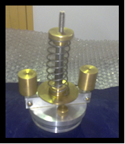
Currently, mechanical governors are still used to maintain constant motor speed. The most effective type is the centrifugal governor, with two common variants: the simple centrifugal governor and the Hartnell centrifugal governor.
The figure below shows the free-body diagram of one half of a simple centrifugal governor.
In the equilibrium state (i.e., rotation at constant angular velocity for the governor), from the free-body diagram, the torque balance yields:
[ text{Sum of torques} = 0 ]
According to the resulting relation, the change in height ( h ) is significant at low speeds. In other words, the simple centrifugal governor exhibits high sensitivity at low speeds. However, it is not suitable for high-speed applications. For higher speeds, the Hartnell governor is more appropriate.
In the Hartnell governor, by rotating an adjusting nut, a spring force can be applied to the system. As a result, the stability of the governor increases (see figure below).
7.
Cam-Follower System
Objective of the Experiment:
To plot the displacement diagram of the follower versus the rotational angle of the cam and to redesign the cam profile.
Theory of the Experiment:
The cam-follower system is one of the essential components in machinery. The cam generates the required motion through direct contact with the driven member, i.e., the follower. The widespread use and importance of cams in machines stem from the fact that the follower’s motion characteristics can be easily modified by changing the cam’s shape.
Moreover, within a single rotational cycle of the cam, the follower can undergo various types of motion—stationary, constant velocity, constant acceleration, variable acceleration, etc.
8.
Free Torsional Vibrations
Objective of the Experiment:
To determine the shear modulus of a shaft based on the period of torsional oscillations and the moment of inertia of a compound system.
Theory of the Experiment:
When a shaft transmits power, it is subjected to torsional moments, resulting in angular deflections. If the applied torque varies with time, the shaft experiences torsional vibrations. If the frequency of the applied torque matches the natural frequency of the shaft’s torsional vibrations, resonance occurs. This leads to a significant increase in the amplitude of torsional oscillations, potentially causing damage to the shaft.
Torsional vibration may occur independently or simultaneously with transverse vibration of the shaft.
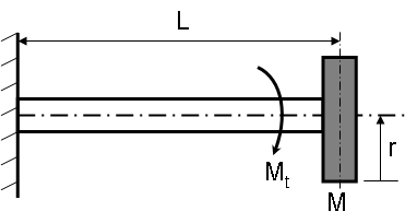
The simplest case of torsional vibration involves a single torsional oscillation of a cantilevered shaft with a disk of moment of inertia ( I ) attached to its free end (see figure below).
9. Automobile Suspension System
Objective of the Experiment:
To examine the vibrational behavior of a vehicle suspension system and the reason for using shock absorbers.
Theory of the Experiment:
Nowadays, passenger comfort is the top priority for car manufacturers. One of the most important factors in passenger comfort is preventing the transmission of road-induced vibrations to the occupants. To achieve this, a suspension system is installed between the vehicle’s chassis and its wheels.
The suspension system includes springs, shock absorbers (dampers), and all mechanisms used to ensure comfort and vehicle handling.
Every suspension system has two main goals:
- Passenger comfort
- Vehicle handling and control
The first goal is achieved by isolating passengers from road irregularities, which is done using flexible components like springs and damping elements such as shock absorbers. In fact, most of the work is done by the springs. Shock absorbers are used to dampen the oscillations of the springs after encountering road bumps. Without shock absorbers, the car would continue to oscillate repeatedly with relatively large amplitude after hitting a bump, which is unpleasant for passengers.
The second goal is achieved by preventing the vehicle from rolling or bouncing and maintaining tire contact with the road. This is done using mechanical arms that connect the axle or wheels to the body or chassis.
The dynamic properties of a suspension system are crucial for vehicle motion behavior and its response to forces and moments transmitted from the tires to the chassis.
In fact, the suspension system is one of the components of the chassis unit in every light or heavy vehicle, located between the transverse axis of wheel power transmission and the vehicle body.
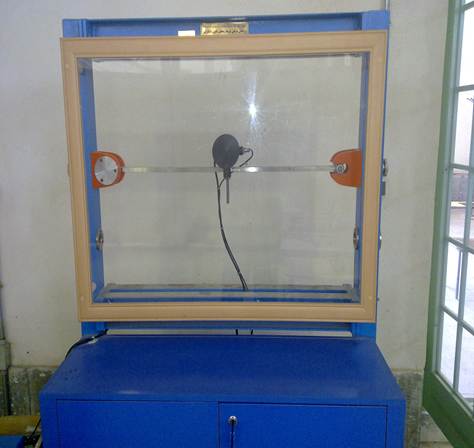
Test System Description:
In the damper test system, the wheel moves over a simulated road surface. Road irregularities are simulated by applying impacts through a lever placed between the wheel and the simulated road.
The system used in this experiment rotates the wheel using a speed controller, adjustable from a minimum of 165 rpm to a maximum of 1100 rpm, equivalent to a linear speed of 120 km/h. The speed is manually and continuously adjustable and readable on the corresponding indicator.
- Outer diameter of the wheel: 545 mm
- Length of the vertical arm from the bump displacement point: 515 mm
- Distance from the pivot to the sensor mounting point: 390 mm
Three types of simulated bumps made of special PVC (non-abrasive under the wheel) are used, with diameters of 20, 25, and 30 mm. They are mounted either by threading or manual force.
Both ends of the bumps have retention holes in grooves so they can be replaced and reused after wear.
Software Used:
The ADAM View simulation software was used in this experiment. A complete guide to using this software is provided in the appendix.